- Introduction
- Getting started
- Defining services
- Networks
- Hosts
- Routers
- Interfaces
- Security zones and aggregates
- Referencing network resources
- Groups
- Automatic groups
- Groups of protocols
- Areas
- Path restrictions
- Dual stack objects with combined IPv4 and IPv6
- Automatic dual stack hosts from pure IPv4 hosts
- Network address translation (NAT)
- Secondary packet filters
- Local packet filters
- Outgoing ACL
- Logging
- Routing
- Rerouting inside a security zone
- Virtual interfaces
- Crosslink network
- Protocol modifiers
- Keyword “foreach” in services
- Subnet relation between networks
- Policy distribution point
- Disable generation of object-groups
- Defining crypto tunnels
- Changing default values of command line switches
Policy language
Introduction
Netspoc reads a policy and generates configuration files for packet filters. The policy is written in Netspoc’s policy language. The policy consists of a network topology and a set of services. A service is a set of related rules which describe the traffic permitted between some network resource and its users.
The policy is either read from all files inside a directory or from a single file.
Getting started
We start with a simple example having one service and a topology which only consist of a few networks.
Service to access WWW servers
A service defines one or more related rules which describe access to
(or from) a resource.
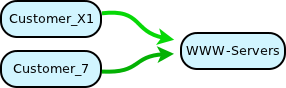
service:WWW-access = {
 description = Access of customers to WWW servers network
 user = network:Customer_X1, network:Customer_7;
 permit src = user;
        dst = network:WWW-Servers;
        prt = tcp 80;
}
This service has a single rule. It permits a set of users as
source to access a destination network with protocol tcp 80.
In general, all rules of a service must reference the keyword
user. This ensures that the rules operate on the same resource.
A small topology
The topology is built from networks and routers, connected by interfaces. For Netspoc, a network is a logical IP network with IP address and prefix length. A router is any device which routes IP packets. Netspoc generates configuration files for managed routers. Unmanaged routers are only used to connect networks.
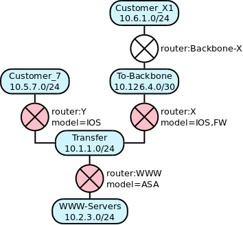
network:Customer_X1 = { ip = 10.6.1.0/24; }
router:Backbone-X = {
 interface:Customer_X1;
 interface:To-Backbone = { ip = 10.126.4.2; }
}
network:To-Backbone = { ip = 10.126.4.0/30; }
router:X = {
 managed;
 model = IOS, FW;
 interface:To-Backbone = { ip = 10.126.4.1; hardware = FastEthernet1; }
 interface:Transfer    = { ip = 10.1.1.9;   hardware = FastEthernet0; }
}

network:Customer_7 = { ip = 10.5.7.0/24; }
router:Y = {
 managed;
 model = IOS;
 interface:Customer_7 = { ip = 10.5.7.1; hardware = FastEthernet1; }
 interface:Transfer   = { ip = 10.1.1.8; hardware = FastEthernet0; }
}

network:Transfer = { ip = 10.1.1.0/24; }
router:WWW = {
 managed;
 model = ASA;
 interface:Transfer    = { ip = 10.1.1.109; hardware = GigabitEthernet0; }
 interface:WWW-Servers = { ip = 10.2.3.1;   hardware = GigabitEthernet1; }
}
network:WWW-Servers = { ip = 10.2.3.0/24; }
The connection between network and router is established by repeating the network name as interface name.
A managed router has additional attributes, which are used to generate device specific code:
modeldefines the type of the device. E.g.IOS, FWmeans IOS router with stateful inspection enabled.- Each interface needs an IP address.
hardwareof an interface gives the device’s denotation of that interface.
Apply Netspoc to an example
Save both, service and topology into a file named example and call Netspoc like this:
netspoc example code
This generates configuration files for device X,
device Y and device WWW
in a newly created directory named code.
The generated files contain commands to configure packet filters rules and static routes matching the model of each device.
- Since device Y uses stateless packet filters, Netspoc automatically generates a rule to permit answer packets.
- For device of model ASA, object-groups are created.
Defining services
Rules describe, which traffic is permitted to flow between different network resources. In Netspoc, related rules are grouped into services. All rules belonging to a service must use either the same source or destination resource(s). This is enforced by the keyword “user” which must be referenced either from source or from destination or from both parts of a rule.
Rules
A rule permits or denies traffic of some protocol to flow from source to destination. Source and destination are one or more network resources.
Each occurrence of the keyword “user” is substituted by its definition. This is typically a group of values.
It doesn’t matter in which order the rules are written. Netspoc places deny rules always in front of all permit rules.
Protocols
Simple protocols like “tcp 80”, “udp 161-162”, “protocol 50” can be used directly in rules.
You can define named protocols like
protocol:HTTP = tcp 80;
and use “protocol:HTTP” instead of “tcp 80” in a rule.
Details
For TCP and UDP, if two ranges are given, they describe source and destination port.
Only one rule is needed to permit a TCP connection from source to destination. Answer packets are automatically allowed. For stateful packet filters, this is done at the device. For stateless packet filters, Netspoc automatically generates a rule which allows any TCP traffic from destination to source with flag “established” i.e. no SYN flag set.
Similarly, only one rule is needed to let UDP packets pass from source to destination and back. For stateless packet filters, a rule with reversed addresses and reversed port numbers is generated.
For protocol IP and stateless packet filters, a rules with reversed addresses is automatically generated. This is done to get an consistent handling for TCP, UDP and IP.
Networks
A network has an IP address with prefix length. It contains any number of host definitions.
Alternatively a network can be unnumbered. An unnumbered network must have no host definitions at all. It must be connected to at most two interfaces which all must be unnumbered. An unnumbered network must not be used in rules.
Hosts
Hosts represent servers or clients inside a network. A host has an IP address or a range of IP addresses. The IP address(es) must match the address of the surrounding network.
Routers
Routers are connected to networks by interfaces. A router can correspond
- to some physical or virtual router or packet filter
- or to some backbone which simply connects networks.
A router can be managed or unmanaged. An unmanaged router is simply defined to connect some networks.
Netspoc generates access-lists for managed routers. Hence, managed routers need to be defined more accurately since this information is needed for code generation.
Currently these router models are supported:
Linuxfor Linux with iptables,ASAfor Cisco ASA,ASA, VPNfor Cisco ASA with VPN tunnels authenticated by certificates,IOSfor Cisco IOS routers,IOS, FWfor Cisco IOS routers with stateful inspection,PAN-OSfor Palo-Alto firewalls,NSX, T0for VMWare NSX tier 0 gateways,NSX, T1for VMWare NSX tier 1 gateways.
Interfaces
In Netspoc’s policy language, interfaces have no name of their own. Instead a network name is used to indicate which network an interface is linked to.
Vendor specific interface names like ‘eth0’ or ‘FastEthernet3’ are put into the ‘hardware’ attribute. This attribute is mandatory for managed routers. If multiple logical IP networks are attached to a single hardware, these are modelled as different Netspoc interfaces, using the same hardware attribute.
An interface can have one or more IP addresses. All of them must match the IP/mask of the corresponding network. An unnumbered interface must only be linked to an unnumbered network. A negotiated interface has an unknown IP address out of the attached network. If an interface with negotiated IP is used in a rule, the address range of the attached network is taken.
Additional IP addresses can be defined using a secondary
interface.
Another method to define secondary interfaces is by giving two or more IP
addresses to the primary interface. This implicitly defines secondary
interfaces with a name which is derived from the name of the primary
interface by adding an incrementing number beginning with “2”.
This is equivalent to define
secondary:2 = {...}, secondary:3 = {...}, ....
A virtual interface defines a shared IP address between two or more routers. See Virtual interfaces for details.
Use attribute ‘loopback’ to define a loopback interface. A loopback interface is not linked to a network, but only used as an additional address of a router. Loopback interfaces of different routers may share the same name, e.g. interface:r1.loop and interface:r2.loop.
For interface definitions of unmanaged routers, all attributes can be left out. An interface definition without any attributes is called a “short interface definition”.
Security zones and aggregates
The topology is partitioned by managed routers which act as security gateways. Each partition consists of a single network or a set of networks, which are connected by unmanaged routers. We call these partitions “security zones”. An aggregate represents all networks inside a security zone.
If some network:N is located inside a security zone, the corresponding
security zone can be referenced by any:[network:N].
Use an aggregate as source or destination of a rule to create a wildcard ACL line with IP 0.0.0.0/0. This can be used to create optimized access lists.
We use the type ‘any:’ for aggregates, because the resulting ACL lines with wildcard address 0.0.0.0/0 are written as ‘any’ on Cisco devices.
It is possible to define a named aggregate any:X by linking it to some
network or unmanaged router inside a security zone.
Matching aggregates
An aggregate can optionally be restricted to a network match.
This is best be explained by an example.
Suppose, a security zone has a large number of networks. A part of
these networks has IP addresses 10.42.x.0/24. You can create wildcard
ACLs matching 10.42.0.0/16 by defining an aggregate with attribute
ip = 10.42.0.0/16. This aggregate matches all networks inside the
corresponding security zone with matching IP addresses.
Referencing network resources
Network resources can be used as source or destination in rules. Network resources are:
- networks
- hosts
- aggregates
- interfaces
Hosts, networks and aggregates are referenced by the name of their respective definition.
When referencing interfaces, we need to use a different syntax
than for interface definitions: the router name followed by a network
name interface:<router-name>.<network-name>.
A reference to a secondary interface has three parts: the
router name, the network name and the name of the secondary interface
from its definition
interface:<router-name>.<network-name>.<secondary-name>.
Groups
An implicit group defines a set of network resources. In the simplest case it is a list of comma separated network resources. This list can be used directly as source or destination of rules.
If the same list of resources is used again and again in different rules, you should define a named group. A named group is defined once and can be referenced by different rules. If the resources change, the list has to be changed only once.
More complicated groups can be build using intersection and complement. Intersection and complement is typically used to remove some elements from a given set of elements.
The definition of a named group can reference other groups.
It is allowed to define an empty named group.
Automatic groups
Automatic groups are used to derive a set of network resources by graph operations directly from the topology.
Selectors [auto] and [all] can be used as network part when referencing an interface.
- [all] denotes all interfaces of a router.
- [auto] denotes the interface which points to the other object in a rule. If a router is part of a cyclic subgraph then there can be multiple paths to the other object. In this case [auto] denotes multiple interfaces.
-
[managed & …].[all auto] restricts the result to interfaces of managed devices.
But note: Unnumbered interfaces are silently removed from these results.
-
network:[interface:x.y]takes the network attached to interface:x.y. -
network:[host:x]takes the network wherein host:x is located. -
network:[network:x]is equivalent tonetwork:x. -
network:[any:x]takes all networks located inside security zone any:x. -
network:[area:x]takes all networks located inside area:x. -
any:[interface:x.y], any:[host:x], any:[network:x],
any:[any:x]
takes the security zone wherein the inner object is located. -
any:[area:x]takes all security zones located inside area:x. -
interface:[network:x].[<selector>]results in all | auto interfaces attached to network:x. -
interface:[interface:x.y].[<selector>]is equivalent tointerface:x.<selector>. -
interface:[any:x].[all]takes all border interfaces of security zone any:x. -
interface:[area:x].[<selector>]results in interfaces which are located inside area:x. Note: Border interfaces are left out, but inclusive_border interfaces are part of the result. -
host:[network:x]results in all host defined inside network:x. -
network:[...],any:[...],interface:[...]orhost:[...]applied to a set of objects is equivalent to applying these to the single elements and taking the union of results. E.g.network:[host:a, host:b]is equivalent tonetwork:[host:a], network:[host:b]. -
Auto interfaces, i.e. with selector
[auto]must only be used at top-level and not as inner object of other automatic groups. There is one exception from this rule:interface:[interface:x.[auto]].[auto]is allowed.
Groups of protocols
A named protocol group defines a set of simple or named protocols. A Protocol group can reference other protocol groups and it can be empty. Intersection and complement is not defined for protocol groups.
Areas
An area denotes a part of the topology which is delimited by a set of managed interfaces. An area typically spans multiple security zones. Areas are used
-
to easily denote all networks or security zones of some part of the topology,
-
to inherit attributes
natorownerto enclosed security zones and networks or -
to inherit
router_attributesto managed routers inside the area.
Use attributes border or inclusive_border to define interfaces
which are border of the area. border is exclusive. The router of the
border interface will not be part of the area. The area starts at the
security zone attached to the border interface.
If you use inclusive_border, the router of the border interface is
part of the area. The area starts at the router attached to the
border interface. This is useful if a router has more than two
interfaces and all but one interface X should be part of the
area. Then define X as inclusive_border of this area.
Alternatively use attribute anchor to define a starting point from
where the area extends. Use attribute anchor to define an area which
stretches across the whole topology.
An area must be defined by using either attribute anchor or one or
both of attributes border and inclusive_border.
Only interfaces of managed routers must be given as border or
inclusive_border.
network:[area:X] denotes the group of all networks inside area X.
Use any:[area:X] to get the group of all security zones inside area X.
Path restrictions
In a topology with cyclic subgraphs, there are multiple paths available between source to destination. Per default, Netspoc chooses all available paths and generates filter rules for all devices on all paths.
Path restrictions are used to restrict paths inside cyclic subgraphs. All paths traversing two or more interfaces belonging to the same path restriction are discarded i. e. marked as invalid. Path restrictions must not be used to discard all paths between some source / destination pair. Use a service with deny rules instead. A path restriction must only be applied to interfaces located inside or at the border of a cyclic subgraph of the topology.
A path restriction is automatically added for each group of interfaces belonging to a VRRP or HSRP cluster.
Dual stack objects with combined IPv4 and IPv6
It is possible to define dual stack objects, having both, IPv4 and IPv6 addresses. This simplifies the modeling of a dual stack topology. Otherwise it would be necessary to model a separate IPv4 and IPv6 topology.
Rules between dual stack objects will generate ACLs for IPv4 and IPv6. Rules between dual stack object and pure IPv4 object will silently ignore IPv6 address and generate only ACL for IPv4.
These attributes are used to define dual stack objects:
ip6at network, host, interface and aggregate.range6at host.unnumbered6at network and interface.negotiated6at interface.
Other changes resulting from use of dual stack objects:
- If dual stack objects are used as border or inclusive border of an area, this defines two areas with identical name: one in IPv4 topology and one in IPv6 topology.
- If dual stack objects are used as interfaces of a pathrestriction, this also defines two pathrestrictions in IPv4 and IPv6 topology. If the second pathrestriction has only one interface or only interfaces outside of a loop, it is silently ignored.
- New attributes
ipv4_onlyandipv6_onlymay be used at service or area. This will enable only IPv4 or IPv6 part of dual stack objects. - The following attributes are applied only to IPv4 part
if used in dual stack objects:
nat,nat_in,nat_out,subnet_of,hub,spoke`.
Automatic dual stack hosts from pure IPv4 hosts
In dual stack networks with many hosts, the IPv6 address is often derived from its IPv4 address.
The attribute auto_ipv6_hosts is used to automatically generate
dual stack IP from pure IPv4 hosts.
It will generate IPv6 addresses for hosts
by combining its IPv4 adress with the IPv6 address of its network.
These attribute values are provided:
auto_ipv6_hosts = readable;
Example:
network:ip6 = 2001:db8:1:1::/64;
host:ip = 172.17.1.48;
=> 2001:db8:1:1:172:17:1:48auto_ipv6_hosts = binary;
Example:
network:ip6 = 2001:db8:1:1::/64;
hosts:ip = 172.17.1.48;
=> 2001:db8:1:1::ac11:130auto_ipv6_hosts = none;
No IPv6 address is generated
This attribute is valid at network, area and host.
Network address translation (NAT)
Network address translation occurs at routers. At one side of a router, a network resource is visible with its original IP address; at some other side this address is translated to a different address.
Currently, Netspoc supports static and dynamic NAT for whole networks.
For static NAT, the translated address uses the same net-mask as the original network. The translation is automatically applied to all host and interface definitions of the translated network. A separate NAT definition for hosts or interfaces is not permitted in this case.
For dynamic NAT, the translated address can have a different net-mask than the original network. Typically a smaller network is used for translation. IP addresses are translated dynamically, hence hosts and interfaces of this network are not addressable from outside. But a dynamic translation of a network can be augmented by static translations for single hosts or interfaces of this network.
Syntax for NAT is divided into two parts:
- NAT definition
- specifies the translated IP address of a network resource.
- NAT binding
- applies a set of NAT definitions to an interface.
Example
network:extern has improper IP addresses, which are not usable at network:intern. router:r_ext performs static NAT. The NAT definition and NAT binding tells Netspoc, that and where NAT occurs. host:extern_www and host:extern_mail are visible with addresses 10.7.128.10 and 10.7.128.25 from network:intern.
network:extern = {
 ip = 128.1.2.0/24;
 # static NAT definition
 nat:bad128 = { ip = 10.7.128.0/24; }
 host:extern_www = { ip = 128.1.2.10; }
 host:extern_mail = { ip = 128.1.2.25; }
}

router:r_ext = {
 interface:extern;
 interface:intern = {
  ip = 10.1.1.1;
  # NAT binding
  nat_out = bad128;
 }
}

network:intern = { ip = 10.1.1.0/24; }
All NAT definitions with the same name establish a set of NAT definitions. A set of NAT definition is effective behind that interface where the NAT binding with the same name occurs. We are defining behind an interface as that part of the topology which is seen when looking from the router to that interface.
Multiple NAT definitions can be given for a single network. These are bound to different interfaces to make different NAT definitions effective at different parts of the topology.
Multiple NAT definitions can be bound to single interface. This simplifies definition of NAT for devices with multiple interfaces.
For dynamic NAT, multiple networks can use identical NAT definitions. This is used to masquerade multiple networks to a single address space.
Use dynamic NAT as attribute of an area definition, to apply the same NAT definition to all networks located inside the area. If some networks of the area already have a NAT defintion with the same name, the original definition is retained. Use identity NAT at network level to exempt some network from NAT at area level.
Netspoc needs to know about NAT for these reasons:
- When generating ACLs for an interface it must use those IP addresses which are visible in the area attached to this interface.
- The same is true when generating static routing entries.
But the actual NAT commands have to be configured manually.
Attribute acl_use_real_ip
Use attribute acl_use_real_ip for ASA from version 8.3 or later.
Netspoc uses real IP and not translated IP when creating ACLs.
Secondary packet filters
In a given topology we can get chains of managed packet filters on the path from source to destination. By default, each device filters the same rules again and again.
A secondary packet filter gets a simpler rule set.
If there is at least one standard packet filter on the path from source to destination, all secondary packet filters on this path get a simplified ACL line for the current rule. This ACL line allows
- any IP packets,
- the whole source network and
- the whole destination network.
This simplified filtering assures that the traffic comes from the correct source and goes to the correct destination.
If, for a given rule, there is a chain of secondary packet filters without one standard filter, all devices do standard filtering.
A secondary packet filter is declared with attribute
managed = secondary. This can be useful if a router has not
enough memory for storing a complete set of filter rules and most of
the packets get fully filtered already by some other managed device.
If a device is marked as managed = primary, all rules which pass
this device, are implemented as secondary filters on other devices
which are marked either as “standard” or as “secondary”. The effect
of “primary” can be overridden by choosing the filter type “full” at
an other device.
The default filter type for devices which are simply marked as “managed” is “standard”.
Local packet filters
Suppose you have some local networks with IP addresses 10.11.1.0/24, 10.11.2.0/24, …, belonging to some larger IP address range 10.11.0.0/16. All these networks are supposed to be connected by one or more local packet filters. There are external networks with other IP addresses. Standard packet filters connect the external networks with some local networks.
In this topology, the local packet filter needs only to check packets, where source and destination address match 10.11.0.0/16. All other packages from or to external IP addresses can pass unfiltered, because these packets have already been filtered by standard packet filters.
A local packet filter is declared with attribute “managed = local”. An additional attribute “filter_only” defines the list of the to be filtered IP address ranges.
For a local packet filter with “filter_only = 10.11.0.0/16;”, Netspoc generates reduced ACLs:
- standard deny rules (if used)
- permit traffic between local networks
- deny ip 10.11.0.0/16 10.11.0.0/16
- permit ip any any
A packet filter is declared as “local” for two purposes:
- Get a reduced number of ACL entries for devices not capable to handle many ACL entries.
- Allow external traffic, which enters through some other packet-filter not managed by Netspoc.
All networks located inside a security zone connected to a local packet filter must match “filter_only”. But other security zones are allowed to contain networks matching “filter_only”. In this case, the optimization becomes less effective. Multiple local packet filters connected directly, without a standard packet filter in between, must use the same values for “filter_only”.
If traffic is filtered only by one secondary and one local packet filter then the secondary filter does standard filtering.
If attribute “filter_only” has N values, then we would get NxN deny rules for each source/destination pair. But for a leaf security zone, only connected to one local packet filter, we already know that each source address matches “filter_only”. Hence we deny any source address in this case:
- deny ip any 10.11.0.0/16
Outgoing ACL
By default, Netspoc generates incoming access lists at each interface
of a managed device. Use the attribute no_in_acl at one
interface, to move the incoming ACL from this interface to outgoing
ACLs at the other interfaces of the same device.
This is useful for situations like this:
- The packet filter connects multiple customers to some central site. Each customer needs to inspect the ACLs of ‘his’ interface, but must not see ACLs of the other customers. Declaring the interface to the central site with ‘no_in_acl’ adds outgoing ACL to each customers interface.
- The packet filter has three interfaces A, B, C. There is a rule
permit network:A -> any:[network:B]. With only incoming ACLs, this would allow traffic from network:A to any:[network:C] as well. With attributeno_in_aclat interface A we get outgoing ACLs at interface B and C which permit traffic to any:[network:B] but not to any:[network:C].
For IOS there remains a minimal incoming ACL that filters traffic for the device itself.
These restrictions apply:
- At most one interface with
no_in_aclis allowed per device. - Multiple interfaces at the same hardware are not allowed if
no_in_aclis declared at some logical interface of this hardware. no_in_aclmust not be used together with crypto tunnels at the same device.- All interfaces must equally use or not use outgoing ACLs at a crosslink network.
- All interfaces with attribute
no_in_aclat routers connected by a crosslink network must be border of the same security zone.
Outgoing ACLs are supported for model IOS and ASA.
Logging
Logging can be controlled by log attributes:
log_default: Add logging to each rule of a device.log_deny: Add logging to each deny rule of a device.log:<tag>: Change logging individually for each combination of managed device and rule.
Give one or more log definitions log:<tag> at devices, where
logging should be enabled. With <tag> being some valid identifier.
Define attribute log = <tag1>, ...; at each rule that needs logging.
A rule with logging for <tag1> is logged at each device, where a
matching log:<tag1> is defined.
For some devices these attributes accept one or more log modifiers as value that control the behaviour of logging.
Model ASA allows a single modifier alerts | critical | debugging | disable |
emergencies | errors | informational | notifications | warnings. The
severity names correspond to well known UNIX log severities. The
special name disable disables logging for a rule.
Model IOS allows a single modifier log-input.
Model NSX accepts a single modifier tag:VALUE.
This uses the given value as label when logging.
Model PAN-OS accepts one or more of these modifiers
startleading to<log-start>yes</log-start>endleading to<log-end>yes</log-start>setting:SOME-VALUEleading to<log-setting>SOME-VALUE</log-setting>Example:start, end, setting:Panorama.
Routing
Static routing
From its knowledge about the topology, Netspoc generates static routing entries for each managed device.
Routing entries are generated for all network resources, which are used in some rule. I.e. no routing entries are generated for unused parts of the topology. Even for resources which are only used as source of a rule, routing entries are generated, since stateful packet filters implicitly allow answer packets back to the source.
If an aggregate is used in a rule, routing entries are generated for all networks which are located inside the corresponding security zone.
An interface of an unmanaged router must have an IP address, if there is some managed interface with static routing enabled in the same network. We need this requirement for getting all routing entries generated.
Dynamic routing
If an interface of a device has an attribute
routing=<routing protocol>,
no static routing entries are generated for networks
reachable by that interface. Access control lists for this interface
are automatically augmented to permit incoming packets of the routing
protocol. Currently EIGRP and OSPF are supported.
If routing=dynamic is set, no routing code is generated for this
interface. Some other means (e.g. BGP) has to be used to get routes at
this interface.
Use routing=manual at router level to disable generation of routing
code for the whole device. Manually defined routes are left unchanged
by Netspoc-Approve in this case.
Default route
Netspoc can reduce the number of static routing entries per device by automatically inserting a default route. For each device it finds the hop, where the largest number of routing entries points to and replaces them with a single default route to this hop.
This behaviour can be switched on or off by option --auto_default_route.
This behaviour is automatically disabled for a device
- where at least one interface has dynamic routing enabled or
- if already a real static route to some network with IP 0.0.0.0/0 was found.
Rerouting inside a security zone
Internal traffic which flows inside a security zone isn’t filtered at all. In some cases, an interface X of a managed (filtering) router is used as a default route for traffic which normally flows inside a security zone. This would cause internal traffic to be routed to X. Interface X would deny this traffic.
You can handle this case by defining an attribute reroute_permit at
a managed interface. Value of this attribute is a list of networks,
for which any internal traffic should be allowed.
Example
router:x is managed, router:y is unmanaged.
router:x -- network:a -- router:y -- network:b
network:a and network:b are inside the same security zone, since
router:y isn’t managed. If traffic from network:a to network:b is
routed first to router:x and then to router:y, router:x would deny
this traffic. Use reroute_permit = network:b at interface:x.a to
permit any incoming traffic to network:b.
Virtual interfaces
A virtual interface defines a shared IP address between a group of two or more redundancy interfaces. The virtual interface definition is repeated at each member of the group of redundancy interfaces.
The virtual interface can be referenced in rules by appending “.virtual” to the name of the original interface (e.g. interface:r.net.virtual).
The virtual IP address is used as next hop address when generating static routes.
A virtual IP must be different from real IP address(es). It is valid to define an interface having only a virtual IP, but no real IP address.
The type of redundancy protocol can optionally be declared. Redundancy protocols VRRP and HSRP are supported. In this case, ACLs for the associated real interfaces are automatically augmented to permit incoming packets of the redundancy protocol.
If the protocol is declared, an optional id attribute with a numeric
value can be declared. It is used for consistency checks but currently
it is not used when generating code for managed devices.
Crosslink network
Add attribute crosslink to a define a crosslink network.
A crosslink network combines two or more routers to a cluster of routers. Filtering occurs only at the outside interfaces of the cluster. The crosslink interfaces permit any traffic, because traffic has already been filtered by some other device of the cluster. These characteristics are enforced for crosslink networks:
- No hosts must be defined inside a crosslink network.
- All attached routers are managed and have the same managed type (secondary, standard, full, primary).
- A crosslink network must not be used in rules.
- A hardware interface attached to a crosslink interface has no other logical networks attached.
- Crosslink networks are silently removed from automatic groups.
Protocol modifiers
One or more protocol modifiers can optionally be appended to a named protocol definition. A protocol modifier modifies the rule in which the corresponding protocol is used as follows:
- stateless
- The rule is only applied to stateless devices.
- oneway
- At stateless devices, don’t automatically generate rules to permit answer packets.
- reversed
- Source and destination are swapped.
- dst_net
- If destination of rule is a host or interface, find the enclosing network N and replace destination by N. Exception: hosts having a VPN id and interfaces of manged routers are left unchanged.
- src_net
- Equivalent to dst_net modifier but applied to source of rule.
Keyword “foreach” in services
With the keyword “foreach”, the substitution of keyword “user” occurs repeatedly for each element of the definition of “user”. Used together with automatic groups, this feature allows to define rules between elements and their neighbourhood.
Example
service:ping_local = {
 description = Allow ping to my_devices from directly attached network
 user = foreach interface:[group:my_devices].[all];
 permit src = network:[user]; dst = user; prt = icmp 8;
}
Subnet relation between networks
All networks must be disjunctive if option ‘check_subnets’ is active. This can be useful for a large topology, where a network can easily be redefined by mistake. Exceptions must be declared explicitly:
- has_subnets: This network can enclose other networks.
- subnet_of: The enclosing network is declared explicitly.
Policy distribution point
A server, which distributes the Netspoc generated configuration to managed devices is called “policy_distribution_point”. Inside a topology one or more policy distribution points can be used. Use attribute “policy_distribution_point” at routers or at “router_attributes” of areas to define a policy distribution point for each device.
This allows Netspoc to know by which IP address a device is reached from the policy distribution point. This IP address is added as a comment to each generated device configuration. It is later used to reach the device when deploying the configuration by Netspoc-Approve.
Disable generation of object-groups
Netspoc generates optimized code using object-groups for devices of
type ASA. Use router attribute no_group_code to
disable this optimization.
Defining crypto tunnels
A crypto tunnel between two interfaces is defined by marking one
interface with attribute hub and the other one with attribute
spoke. The value of both attributes is the name of a crypto
type. This name is used for two purposes:
- Hub and spoke definitions using the same crypto type are linked together.
- Technical details of the crypto tunnel are defined in the corresponding crypto defintion.
A large number of crypto tunnels of a hub and spoke topology can be defined easily. If only a single tunnel is needed, one interface is arbitrarily marked as hub.
Encrypted VPN tunnels are supported for
- remote access by tele worker with software VPN client,
- remote access from remote office with hardware VPN client or
- LAN to LAN tunnel.
Access lists at crypto tunnels
For devices of type ASA or ASA,VPN, incoming traffic of crypto
tunnels is filtered at interface ACL. Netspoc uses “no sysopt
connection permit-vpn” to enable filtering of VPN traffic at interface
ACL.
For IOS routers, a separate access-list is used for filtering incoming traffic of crypto tunnels.
Changing default values of command line switches
The behavior of Netspoc can be adjusted using command line switches.
See man netspoc for details.
You can change values for command line switches permanently for a project by adding a file named “config” in the toplevel directory of the Netspoc configuration.
Format of the “config” file:
- Assignment
key = value;. Seeman netspocfor valid keys / value pairs. - Comment lines:
# ...