Technical documentation
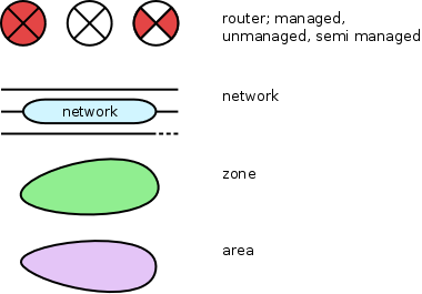
On this page, we are going to develop a technical netspoc documentation describing how Nespoc works internally. The structure of this documentation will follow the Netspoc program procedure, providing a general overview over the program as well as orientation when contributing to the source code. Network architectures are represented and processed by Netspoc as graphs, with routers and networks as nodes and interfaces as edges. For better understanding, several pictures are included in this documentation, using the symbols depicted below. As you might have noticed, there is no symbol for interfaces included. As interfaces are needed whenever a network is connected to a router, we omit their explicit representation.
Netspocs perspective
Netspoc generates ACLs and static routes for a given network policy, consisting of a set of services and a network topology. It does so by finding all paths inside the network topology for a certain source and destination pair specified in a rule from the service set. It is important to notice, that the network topology best fed to Netspoc is not necassarily an exact copy of the real network. Instead, the input topology should be a model of the network that provides just as much information as needed for Netspocs purpose. For example, complex parts of the network with dynamic routing and without filtering are not affected by Netspoc at all. They should therefore be replaced in the input topology by a single unmanaged router. This saves time and space during compilation and is easier to maintain. In very complex network topologies, even constellations may occur where it is suitable to include parts of the network twice to reduce complexity. As long as the ACLs and static routes are not affected, that would also provide a valid model of the network.
When the abstract topology model created by the user is handed over to Netspoc, Netspoc takes several steps to transform it into a graph representation to work on. As before, this representation is not designed to reproduce reality, but to represent those aspects of the topology that are important for generating ACLs and static routes. Moreover, these aspects are modeled to allow completing these tasks as efficiently as possible.
Preparing zones and areas
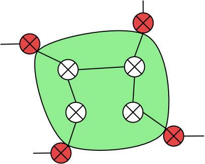
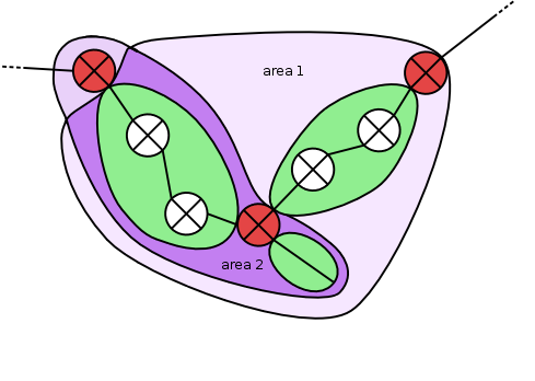
Netspoc combines networks connected by unmanaged routers in zones. These zones, containing networks and unmanaged routers as elements, are delimited by zone interfaces of managed or semi-manged routers. Every zone element is part of exactly one zone. Partitioning the network topology into zones results in several benefits: Zones can be used to define attributes for all networks located in a zone, users may refer to zones as source or destination in rule definition and finally, zones help to speed up the traversal of the graph. As filtering takes place only at zone delimiting interfaces, zones can be traversed instead of single networks.
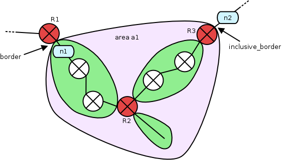
Areas, defined in Netspoc topology by the keyword area, span a
certain part of the network topology, which is enclosed by the areas
borders. The borders of an area refer to interfaces of managed
routers. While a border definition includes the adjacent zone but
excludes the adjacent router from the area, an inclusive_border
definition includes the router but not the zone. Areas are used to
define attributes and NAT information for all included managed routers
and networks and may be used by the user as source or destination in
rule definition.
area:a1 = {
  border = interface:R1.n1;
  inclusive_border = interface:R3.n2;
}
Creating zones
As every network is contained by exactly one zone, all networks are processed, creating a new zone object for every network without a zone. Then a depth first search is conducted beginning at the network and stopping at managed or semi-managed routers, to collect the zones elements and border interfaces of a zone object. References to the zone are set in the collected objects. Zone attributes are set according to the properties of the included networks.
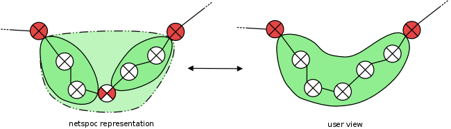
Identifying zone clusters
Netspoc generates a topology representation to find paths between sources and destinations, using zones to accelerate graph traversal. We will see, that Netspoc allows users to refer to security zones in rules. From users point of view, security zones look slightly different from the Netspoc representation though: Semi-managed routers, which are either unmanaged routers with a path restriction or managed routers without filtering, appear as unmanaged routers to the user. Thus, when a user refers to a security zone, a set of networks is supposed that is internally represented as zone cluster. Zone clusters contain zones connected by semi-managed routers and delimited by managed routers.
To generate zone clusters, the zones are processed. If a zone is found that is not included in a cluster, a new cluster object is created. Then a depth first search is conducted, starting at the zone and stopping at managed routers to collect all zones of the cluster. If the cluster contains a single zone only, it is deleted.
The following three steps are not part of zone/area generation, but are placed inside the set_zone function in source code and therefore included here.
Apply no_in_acl declaration
Netspoc allows router interfaces to be tagged as no_in_acl
interfaces, indicating that no ACL is supposed to be generated at the
tagged interface but at the other (outgoing) interfaces of the router
instead. Netspoc distinguishes between logical interface and hardware,
because several networks can be connected to a router via one single
interface hardware. As ACLs are generated for the hardware, all managed
routers with no_in_acl interfaces have to be processed, transferring the
tags to the hardware objects of the tagged interfaces, and marking the
routers other hardware objects to need outgoing ACLs.
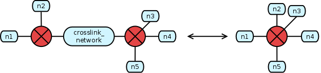
Apply crosslink information
Networks just connecting managed routers may be marked as crosslink networks during topology declaration:
network:crosslink_network = {ip = 10.2.2.1; crosslink;}
Routers connected by crosslink networks act as a single router, causing ACLs to be needed only at the outer interfaces of a crosslinked router cluster. This holds in cases where the clustered routers have equal filter types only though. Otherwise, interfaces of routers with stronger filter types still have to filter information coming from routers with weaker filter types, letting pass more information.
Netspoc processes every crosslink network to identify the adjacent routers with weakest filter strength. The hardware of the appropriate interfaces is then tagged with the crosslink flag, indicating that no ACL needs to be generated.
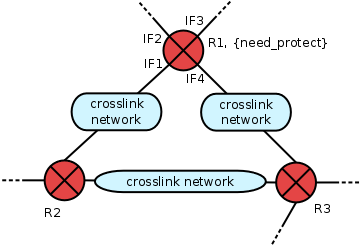
Cluster crosslinked routers
Firewalls recognize, whether the destination of a data packet is the
firewalls interface with IP = 10.1.1.1. or the network with IP =
10.1.1.0/24 connected to this interface, while routers do not. This is
why in router ACLs, access to the interface must be denied if a
permission for the network is given. As Netspoc uses the term router
for both routers and firewalls, router devices that need interface
denial in their ACLs are labeled with the need_protect flag.
When connected by crosslink networks, some of the interfaces of
need_protect labeled routers will not generate ACLs, relying on the
crosslinked routers to do the filtering. Thus, these routers must be
informed about the interfaces of the need_protect-labeled router to
include appropriate deny-clauses in their ACLs.
Netspoc identifies clusters of crosslinked routers containing at least
one router labeled with need_protect. To do so, a depth first search
is conducted, starting at need_protect labeled routers and traversing
routers and crosslink networks only.The interfaces of the clusters
need_protect routers are then referenced in every router of the
cluster.
Preparing area set up
The border interfaces of an area are referenced in the area object. To
set up the areas, Netspoc needs the information whether an interface
is a border or not, to be available at the interface objects
also. Therefore, references to the limited area are set in border
interfaces now. Along the way, routers that are included in an area via
inclusive_border are collected for later use.
Setting up areas
As was seen above, areas are used to set attributes for routers and
networks included by the areas borders. For this purpose, Netspoc has to
identify the networks and managed routers of every area: Starting at
one of the areas borders, a depth first search is conducted,
traversing the adjacent zones and routers and stopping at the areas
border interfaces. The border type of the start interface indicates
the direction of the traversal: If it is of type border, the
adjacent zone is part of the area, while the router is not. If
otherwise the type is inclusive_border the router is included in the
area, but not the zone. Traversed zones and managed routers are collected in
the area object, and references to the area are stored in its zones
and managed routers. If an area object contains no zones, it is deleted.
Netspoc checks for proper border definitions during area set up.
Areas may be defined by the user as anchor areas, that is, without border definitions, but an anchor network instead. This is used to define an area containing the whole topology. Depth first search starting at the zone of the anchor network is used to collect all networks and managed routers.
Finding subset relations
Areas may be nested, with one area being a proper subset of another area. Zones and managed routers included by more than one area always inherit the attributes of the innermost area. For this reason, intersection of two areas can not be allowed.
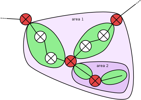
Netspoc detects subset relations by processing every zone contained by one or more areas, identifying all areas containing the zone. Then, each of these areas is compared with the one next in size to check whether every zone inside the smaller area is also contained in the bigger one. A reference to the superset area is added to proper subset areas. If duplicate areas or areas with intersections are found, Netspoc will emit an error message.
Of course, proper subset relations have to hold not only for zones, but also for routers. For most of the routers, proper subset relation has been assured already by proving subset relations for the surrounding zones. If routers are placed at the border of an area though, subset relations can be violated:
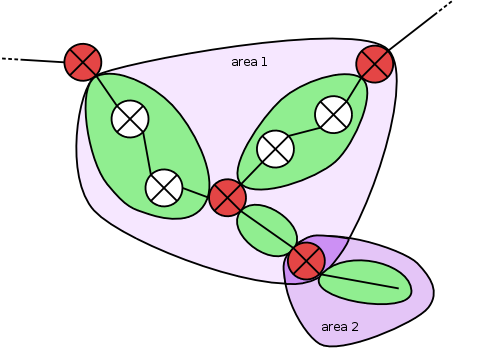
Routers as intersection. To prevent overlapping areas with a
single router as intersection, every router contained via
inclusive_border is processed: each of the areas containing a
certain router as inclusive_border is checked to be in a proper
subset relation with the area next in size regardingthe zones.
Routers with wrong border classification. It might happen that areas forming a proper subset relation regarding their zones are overlapping because a router is included in the smaller area but not in the big one. To find such cases, all areas are processed, checking whether they are a subset of another area. If so, all managed routers of the smaller area are checked to be included in the bigger area also.
Linking aggregates
Users may use the keyword any to define aggregates. Aggregates refer
to a set of IP addresses inside a zone and can be used as source or
destination in rules. Internally, aggregates are represented by
network objects with an is_aggregate flag set. Aggregates include
either all networks of a zone cluster or, if a specific IP mask is
defined, just those networks of the zone cluster matching the
aggregates IP mask. The zone cluster an aggregate refers to is
specified by its link network, which is a network inside the cluster.
any:aggregate1 = {link = network:networkA;}
any:aggregate2 = {link = network:networkB; ip = 10.2.3.0/24;}
Aggregates with no specified IP or IP = 0/0 are used to pass the aggregates nat definition and owner attributes to the included zones.
Netspoc now processes the aggregates, linking them to the zones of the zone cluster. Because aggregate objects hold an array of all networks included by both the aggregare and the linked zone, a new aggregate object has to be created for every zone to avoid all networks of the zone cluster being included in the array. All aggregate objects are stored within the global network hash for later use.
Inheriting area attributes
Area attributes are now passed to the zones and managed routers of an area. To enable inheritance from the innermost area with nested areas, areas are processed in ascending order regarding their size. For every area, router attributes are passed on to the areas routers and NAT attributes are passed to the areas zones. If routers or zones already have an attribute that is to be passed by the area, either because of router/zone definitions or because of inheritance from another (smaller) area, the attribute value is not overwritten. Netspoc generates a warning though if the area and zone/router values of the attribute are equal.
Passing NAT to networks
NAT information is needed within the network objects that are supposed to have address translation. Netspoc therefore processes all zones with NAT definitions and passes them to each of the zones networks. If a NAT attribute of the zone is already set in a network, the networks NAT attribute is not overwritten, but a warning is emitted if the NAT attributes values are equal for both zone and network.
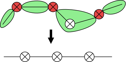
Preparing fast path traversal
Netspoc finds paths inside the network topology. As we have seen above, zones have been applied to accelerate graph traversal, and consistently, we will consider the network topology graph to be build by zones and managed routers (nodes) and interfaces (edges) when it comes to graph traversal. For a clearer representation, we will therefore omit the representation of networks and unmanaged routers in the following pictures. Zones will be depicted as lines and managed routers by an uncolored router symbol instead.
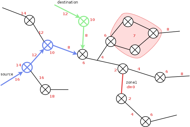
Netspocs approach to path finding
To find paths from a certain source to a destination, the topology
graph is prepared by a single depth first search starting at a
randomly chosen zone1. The distances of the graphs node objects to
zone1 are identified and stored in the respective objects. Then, the
path from source to destination can be easily found by starting at
source and destination nodes, walking towards smaller
distances/zone1 until the paths meet. Loops are contracted to a
single node with a common intermediate distance being applied to all
loop nodes, except for the loop exit to zone1.
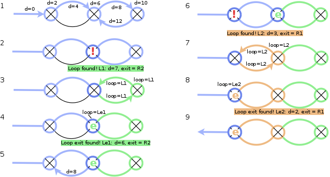
Identifying distances and loops
Netspoc now conducts the depth first search from a randomly chosen
zone1. Within every zone and router object reached, the distance
(x2!) to zone1 is stored. To have the direction to zone1 available
at every node, the interface (for zones/routers) or zone/router object
(for interfaces) leading to zone1 is stored in the node objects.
Whenever a loop is found, that is, a node that has already been
discovered is reached again, a loop object is created (Applying
distances, 10, 14). This loop object contains the node that has been
visited twice as loop exit and the distance of that node to zone1
+1 as loop distance. Then, Netspoc returns from recursion and
references the loop object in the loop variable of all nodes located
on the loop path (Applying distances, 11-12, 15-21). As we want
all nodes inside a loop to be represented as a single node, Netspoc
recognizes nested loops: Whenever Netspoc is on a loop return path and
finds a node already referencing a loop object (Applying
distances, 16), the loop objects are compared. The nodes loop
reference is then set to the object of the bigger loop (that
is, the loop with a lower distance to zone1). Additionally, a
reference to the bigger loop object is set in the redirect variable
of the smaller (nested) loop. Thus, nodes of the nested loop that are not on
the loop path of the bigger loop can be identified later to reset the
loop reference.
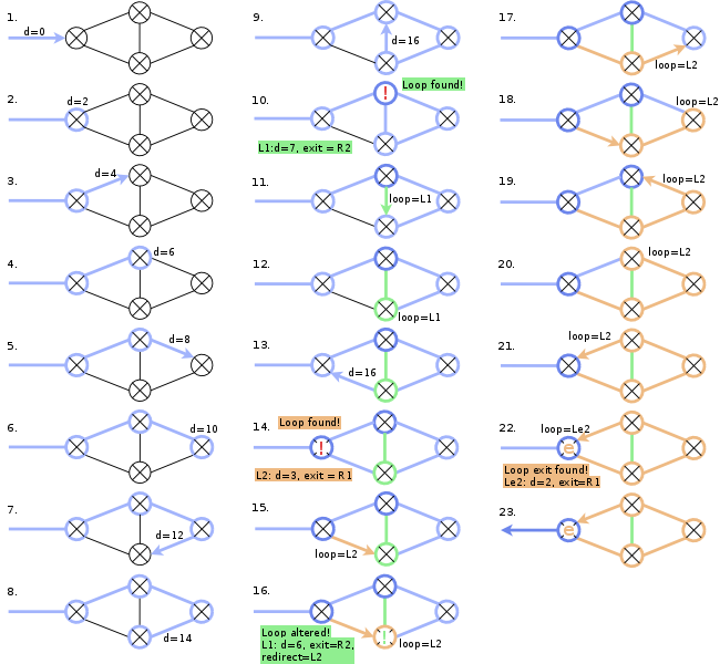
When Netspoc is on a loop return path and reaches the exit node of the loop, a loop exit object is created and referenced in the loop variable of the exit node (Applying distances:, 22). Like the loop object, the loop exit object stores a reference to the exit node and a distance value, which is exactly the distance value of the exit node.
The use of different loop objects for loop nodes and loop exit nodes
shows when a special topology is considered (Cactus loops). In so
called cactus graphs, cycles have single nodes in common. When looking
for paths in such graphs, it is helpful if loops sharing a single node
are represented as different loops and not summarized to one:
Different loop distances help to find the fastes path to zone1.
When Netspoc finds a loop connecting node (Cactus loops, 16)
different objects for loop and loop exit allow to keep the already
found (green) loop and to establish the new (orange) loop and to
preserve the different distances to zone1. Without different
objects, the green loop object would have been redirected to and
included in the orange loop.
Loop preparation
To subsume all nodes of nested cycles within a single loop, Netspoc iterates over all loop nodes. If a node references a nested loop in its loop variable, the reference is reset to the top level containing loop using the information from the redirect variable of the loop object.
Finally, Netspoc clusters all cactus graph loops by adding a reference
to the exit node of the whole cluster as clusterExit to all loop
objects of the cluster.
Possible addition: Picture of clustering
Perform consistency checks
Now that loops are identified and labeled, pathrestrictions and virtual IP addresses, both features that are defined for loops, can be checked for consistency.
Check for proper pathrestrictions
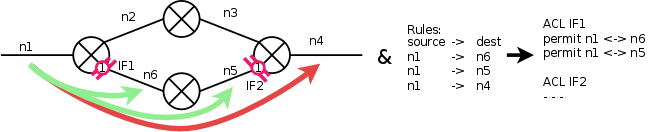
In cyclic graphs, several paths exists from a destination to a source. Per default, Netspoc finds all such paths and generates appropriate ACLs. To exclude paths, pathrestrictions can be defined. Pathrestrictions refer to 2 or more interfaces inside or at the borders of a cycle. Netspoc excludes paths including at least 2 interfaces of a pathrestriction from ACL generation: In the figure below (Pathrestriction), a pathrestrictions is defined for interfaces 1 and 2. Therefore, paths from n1 to n5 and n6 are considered during ACL generation, while the path from n1 to n4 is not. This is reflected in the interfaces ACLs: traffic between n1 and n4 is not routed by these interfaces.
Netspoc assures all defined pathrestrictions to fulfill the requirements and checks that they have an effect on ACL generation. Proper pathrestrictions are then stored in a global array.
Possible addition: When does a pathrestriction affect ACLs?
Check usage of virtual interfaces
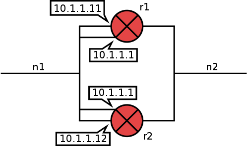
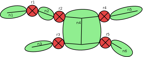
To assure a connection between two networks, they can be connected by more than one router, using HSRP or VRRP and a virtual IP address to establish a redundant connection.
The usage of virtual IP addresses within the topology affects the generation of both ACLs and static routes: Routers sharing a virtual IP address need to communicate to determine which router is active. Therefore the usage of virtual IP addresses will be reflected in the ACLs of the participating interfaces. For the generation of static routes, the interfaces virtual IPs have to be used instead of the real ones.
For this reason, Netspoc policy language allows to model virtual IP addresses:
network:n1 = {ip = 10.1.1.0/24;}
network:n2 = {ip = 10.1.2.0/24;}

router:r1 = {
 interface:n1 = {ip = 10.1.1.11;
                 virtual = {ip = 10.1.1.1; type = HSPR}
                 hardware Ethernet1;}
 interface: n2 = {ip = 10.1.2.1; hardware = Ethernet2;}
}

router:r2 = {
 interface:n1 = {ip = 10.1.1.12;
                 virtual = {ip = 10.1.1.1; type = HSPR}
                 hardware Ethernet1;}
 interface: n2 = {ip = 10.1.2.2; hardware = Ethernet2;}
}
Within the graph representation of topology, the virtual IP address is included more than once, with an additional virtual interface at every participating router (Virtual IP ). Obviously, virtual interfaces are reasonable only within cycles. Therefore Netspoc checks, whether all interfaces sharing a single virtual IP address are located inside the same loop.
Finding active routes
After the elementary rule set has been optimized, static routing information is generated for every (source,destination) pair of the set.
Precalculate next hop interfaces
As was mentioned before, paths are searched and found on an abstract
topology representation, having routers and zones as nodes. When it
comes to routing information thogh, routers within zones are also of
interest. Routing information is attached to every interface of a
managed router (= zone interface) and provides a next hop interface to
a certain destination. Next hop interfaces are not necessarily
interfaces of managed routers, but often located inside zones. As
routing information needs to be generated for every source and
destination pair defined in the rule set, precalculating a general
next hop routing information at zone borders accelerates the process
of route finding. Therefore, setRoutesInZone determines next hop
interfaces to every network of a zone for all zone interfaces. After
the function call, every border interface of the zone holds following
information:
-
Which networks can be reached?
-
What is the next interface (next hop interface) on the path to these networks?
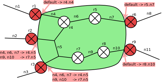
If the path of a (source,destination) pair is known, the interfaces a zone is entered from and left at can be identified and the next hop interfaces can be looked up easily within the interface.
For example,let source and destination be (n2, n11) in the above picture. From a path (r2.n2, r2.n5, r9.n10, r9.n11) through the graph of managed routers and zones can be deduced that the green zone is entered at r2.n5 and left at r9.n10. Looking up n10 in the general routing information at IF r2.n5 we find r7.n5 to be the next hop interface.
To create general routing information at zone border interfaces, all networks at the border of a zone (border networks) are examined. Interfaces of a border network that are not border interfaces of the zone are the networks next hop interfaces. For every next hop interface, a depth first search is conducted to collect all zone networks reachable from the interface. Then, at every zone/border interface of the border network, a lookup hash is stored with reachable networks as keys and hop interfaces leading to these networks as values.
To avoid processing paths several times, a preprocessing step is conducted. Networks reachable from a hop interface without crossing other hop interfaces are collected in clusters via depth first search.
For an example, have a closer look at the picture below: For hop interfaces r4.n4 and r4.n5, cluster1 is reachable without crossing another hop interface, while for next hop interface r5.n5, cluster2 is reachable.
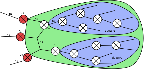
When the main depth first search is conducted, there is no need to process all networks of a cluster repeatedly. Instead, whenever an interface leading to a cluster is processed, all networks of the cluster can be added to the reachable network set at once and search can proceed with the next interface.
Create routing rule set
For routing, the optimized rule set is further reduced. As routing information is calculated for zone borders, mainly the source and destination zone pairs of the optimized rule set are of interest, while protocol information is completely dispensable. Therefore, a pseudo rule is generated for every source and destination zone pair and stored in the routing tree. To generate routing information for the first and last interface of a route, source and destination networks for every pair are extracted from the elementary rule set and stored within the associated pseudo rule. Source and destination zone pairs of rules deleted during optimization are contained within the routing tree because of a containing rule. If however either source or destination or both are interfaces of a managed router, routing information for these interfaces must also be generated. For this reason, deleted rules with such properties are also processed and their source and destination are stored within the pseudo rule.
In the rule set below, rule2 is contained within rule1 and was therefore tagged as deleted.
rule1: action = permit, source = n2, dest = n6, prt = tcp 80-90
rule2: action = permit, source = r1.n2, dest = n6, prt = tcp 80 - deleted
When the rule for rule1 is created, contains the source and destinarion pair of both rule1 and rule2.
pseudo rule: action: permit, source: n2, dest: n6, prt: ---
src networks: n2, dst networks: n6
A closer look at the corresponding topology reveals, that in this case, r1.n2 is an interface of a managed router.
Thus, although rule2s source r1.n2 is an address within n2, it is still a managed interface that needs routing information. Therefore, rule2 needs to be considered in the pseudo rule by additional information:
pseudo rule: action: permit, source: n1, dest: n5, prt: ---
src networks: n2, dst networks: n6,
src interfaces: r1.n2, dst networks for src interfaces: n6
Generate routing information
Every pseudo rule is now processed to generate rule specific routing
information. First, route paths for the rules (source,destination)
pair are found via pathMark. The way this function works has been
briefly touched opon above and will be explained in
detail below. For an abstract zone and router topology, it stores in
every interface on a path from source to destination the next
interface in direction to destination. After the path has been found,
every zone of the path is visited again by pathWalk. This function
applies a given function to every zone or router on path. As it is
repeatedly used within Netspoc, is is described in general
below. In this case, the called function collects a pair
of interfaces for every visited zone, consisting of the interface the
zone is entered from and the interface the zone is left at. For the
first and last zone on path, no pair can be collected, as these zones
are not crossed, but the path starts or ends within these zones
instead. Just one interface is stored for these zones.
Next hop information is generated then for zone interface pairs and single zone interfaces, using the zones general next hop information generated before.
Working on paths
Throughout the Netspoc program workflow, paths from rule sources to destinations are processed several times, for example to generate ACL or routing information for interfaces on a rules path.
To avoid unnecessary calculations, every path is explored only once,
using the pathMark function and information is stored to reconstruct
the path from.
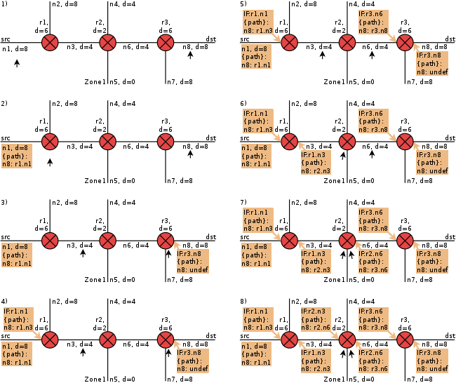
Basically, path mark finds paths from source to destination as has
been briefly explained above. On the abstract
zone/router representation of the topology, it starts from a rules
source and destination nodes (router or zone). From both of these, a
while loop iteratively steps towards zone1 (lower distances, that
is), always taking the next step from the node with higher distance,
until the paths meet. Path information is stored within the interfaces
on path, with every interface holding the next interface towards
destination within the destination specific path attribute. A path
attribute is also created within the source object. Thus, the path can
easily be reconstructed whenever it is to be traversed again. A simple
example of path mark is depicted in the figure below.
Due to special cases like pathrestrictions and loops, the basic algorithm described above has several extensions, that are supposed to be explained in detail.
Marking paths in cycles
For paths leading through loops, path information that is attached to interfaces is not sufficient: within the loop, several paths to a certain destination might exist, beginning at different sources. Due to pathrestrictions, path information valid for one of them is not necessarily valid for the other. The example below shows, that path attributes at interfaces r1.n2 and r2.n2 differ, depending on the source - the path from src1 to dst has to pass the loop clockwise, while a path from src2 is only possible the other way round.
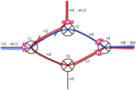
For this reason, path information for the whole loop path is stored at the loop entry node, providing exactly the same information that is otherwise stored within the interfaces in the form of path tuples, holding for every node (zone and router) on the path the interface the node is entered from and left at.
As was touched upon already, the procession of a loop or loop cluster on the path is taking place within a single step of the basic algorithm. Accordingly, within the path attribute of the loop entering interface, the interface the loop is left at is stored as next interface on path and not the next interface inside the loop. For later path reconstruction, a marker is attached to the loop entering interface, indicating that is is required to pass a loop to get to the next interface stored in the path variable.
Of course, the path through the loop still needs to be detected, using
function clusterPathMark. Usually, loop topologies would have
pathrestrictions attached. As pathrestrictions require checks
and tests that obfuscate the underlying algorithm, first assume a
topology without pathrestrictions to explain it:
| 1. | 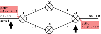 |
During pathMark, a loop node (r4) was found. pathMark stores the path information in the next interface of the linear path and calls clusterPathMark to find the paths from loop exit node (r1) to the detected loop node. |
clusterPathMark is called with a pair of loop nodes that specify
start and end node of a path through the cluster. If neither source
nor destination are located within the loop, the start node is the
loop exit node, and the end node is the node where the loop is entered
from. Then, a depth first search is conducted, beginning at start
node, to find all paths through the loop that reach the end
node. During this depth first search run, only loop nodes are
processed. When the end node has been found, the algorithm returns
from recursion and collects path information. In contrast to the basic
algorithm, path information is not stored within the interfaces on
path but within the first node of the loop. It holds for every
possible path through the loop the interfaces where the loop path
starts and ends as well as tuples describing the path. Every tuple
holds [entrance interface, exit interface] of a router or zone node on
loop path.
| 2. | 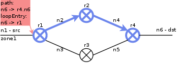 |
ClusterPathMark adds loop entry information to the next interface on path and performs a depth first search on loop nodes, starting at loop exit node (r1). It returns when a path (the initiating loop node) is found. |
| 3. | 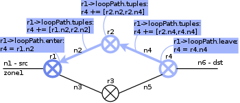 |
As the recursion stack is processed, path information isgenerated and stored within the first node on loop path from source to destination (r1). |
| 4. | 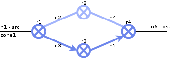 |
Depth first search proceeds until all possible loop paths are tested. |
| 5. | 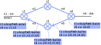 |
Adding further path information to the loop exit node. |
As the depth first search approach can be rather expensive, especially with loop clusters, search space is reduced to those loops that are actually and necessarily passed on the path from source to destination.
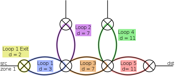
To identify these loops, clusterNavigation is called with the nodes
where the loop cluster is entered and left as arguments. It
identifies paths through the loop cluster in a way similar to the
basic pathMark algorithm. Beginning at the loops of the given
nodes, steps are iteratively taken towards lower distances. Within
every step, a new loop is entered, and a navigation lookup hash is
filled. It stores for every loop those loops that are purposeful to
enter from the actual loop on the path from source to destination. For
the topology above, following hash would be generated:
Loop5      -> Loop5
Loop3      -> Loop3, Loop5
Loop1      -> Loop1, Loop3
Loop1 Exit -> Loop1 Exit, Loop1
The navigation hash is then attached to start node and can be used to
limit search space during clusterPathMark: Whenever a new node is to
be entered during depth first search, the loop of the actual node can
be looked up in the navigation hash. If the loop of the next node is
not within the set of purposeful loops, the node to enter can not lie
on the searched path. It can therefore be excluded from the serach
space.
Dealing with path restrictions
As soon as pathrestrictions are added to the topology, lots of special cases and side effects have to be considered when marking paths.
A closer look at pathrestrictions during pathMark will follow soon!
Just some notes for now:
-
Within every step on the loop path (in
clusterPathMark) pathrestrictions need to be checked. Normal pathrestrictions must be activated at first occurrence, and path exploration must be stopped at second occurrence. At optimized pathrestrictions it must be checked whether the loop node that is to be reached is reachable. -
When entering a loop, it might be a difference whether the loop is entered via a usual or a pathrestricted interface. For the latter, path information is therefore not stored within the loop entry node, but within the interface. The marker at the loop entry interface shows not only, that the path continues on a loop path, but contains also, where loop path information can be found.
-
Usually, path exploration for paths that have interfaces as source or destination starts at the corresponding router node. If source or destination of a rule are pathrestricted interfaces though, the interface is considered to be part of the adjacent zone to achieve equal routes for all IP adresses of the attached network. (Different routes might be found for the interfaces router and zone.) Thus, when checking pathrestrictions, reachability of the zone is of interest. As the loop node that is given as loop exit node to the
clusterPathMarkfunction is a router, additional checks need to be performed.
PathWalk
For a given rule, path walk applies a function that is specified within the arguments at every router or zone node of the path from rules source to its destination. As a very generic function it is used all over the programm to generate and collect information like static routes or ACLs.
If the path for the rules (source, destination) pair is not yet known,
pathWalk calls pathMark to calculate it.
Then, every node of the path is visited, following the path information stored at the interfaces, and the given function is called at every router or zone node, depending on the arguments given.
As with pathMark, loop paths are processed in a single iteration
step of the basic algorithm, processing the path information stored in
the first node of the loop path.